2002 Silverado Brake Line Manual
As a rule, the brake circuits on most vehicles with anti-lock brakes can be bled in the usual manner provided no air has gotten into the ABS modulator assembly. If the only components you replaced were downstream of the modulator (calipers, wheel cylinders, brake hoses or lines), chances are normal bleeding procedures will clear the lines of any unwanted air. Brakes can be bled manually, with a power bleeder, injector tool or vacuum bleeder. It doesn’t make any difference which method you use as long as all the lines and components are flushed with enough fluid to remove any trapped air bubbles or air pockets. The most common bleeding procedure is to bleed the brake furthest from the master cylinder first, then bleed the other brake that shares the same hydraulic circuit (which may be the other rear brake on a rear-wheel drive car or truck, or the opposite front brake on a front-wheel drive car or minivan).

After these have been bled, you then bleed the other brake circuit starting with the furthest brake from the master cylinder. Always refer to the vehicle manufacturer’s recommended bleeding sequence as this may vary from one application to another depending on how the system is configured. Look Before You Leap But what if you replaced the master cylinder, a brake line or valve ahead of the ABS modulator? Or, what if you had to replace the modulator or high pressure accumulator? Now you have a more difficult job ahead of you.
Air can be very difficult to remove from an ABS modulator assembly because of all the nooks and crannies inside the unit. The modulator may have eight to 10, or more, ABS/traction control solenoid valves, plus various check valves and dead-end ports. Some ABS modulators have special bleed screws to help you vent the trapped air when bleeding the system. Others do not and require the use of a scan tool to cycle the ABS solenoids while you bleed the system. To better understand what may be required, let’s look at some bleeding procedures for some common General Motors ABS systems.
The Delco ABS-VI System Introduced in 1991 as an option on Saturn, Buick Skylark, Oldsmobile Cutlass Calais and Pontiac Grand Am models, the Delco ABS-VI anti-lock brake system has been used on a wide range of General Motors front-wheel-drive vehicles, including Chevrolet Lumina and APV, Chevrolet Beretta, Corsica and Cavalier, Pontiac Grand Prix, Sunbird, Oldsmobile Cutlass Supreme and Buick Regal. The Delco VI system is a nonintegral ABS system with a conventional master brake cylinder and power booster. It has four wheel-speed sensors, but is a three-channel system. The front brakes are controlled separately, but the rear brakes share a common ABS circuit.
Attached to the master cylinder is the hydraulic modulator and motor pack assembly. The modulator is held by two banjo bolts at the master cylinder’s two upper outlet ports, and two transfer tubes at the two lower outlet ports. An important service point to note here is that the two lower transfer tubes and O-rings must be replaced if the master cylinder and modulator are disconnected from one another. This is necessary to prevent leaks that could cause the brakes to fail. The modulator assembly has fluid chambers for all four brakes, two isolation solenoid valves, four check balls, a motor pack containing three bidirectional direct current motors with electromagnetic brakes (EMBs) and/or expansion spring brakes (ESBs), three ball screw assemblies, four pistons, a gear drive set and gear cover.
The modulator motor pack, isolation solenoid valves, gear cover and individual gears are all serviceable parts and can be replaced separately. The brakes on GM cars equipped with Delco ABS-VI may be bled using manual, vacuum or pressure bleeding. The usual bleeding sequence is right rear, left rear, right front, left front. Bleeding a Delco ABS-VI System Before you begin, however, you must make sure the rear pistons in the Delco ABS-VI modulator are in the home position so the check balls are unseated.
If this is not done, you won’t be able to bleed the rear brake lines. There are two ways that this can be accomplished: With the Tech 1 or similar scan tool, select the F4 ABS Test mode, then select the F0 “manual control” option. You can now command the rear motor to drive the pistons to the home position. Without a scan tool, open the front bleeder screw at the modulator.
There are two, so be sure you open the front one. Then bleed the modulator. Close the screw, then bleed both front brakes starting with the right one first. After checking for a firm pedal, drive the vehicle above three miles per hour. The controller will automatically reset the system by commanding the rear motor to run to the home position. Once this has occurred, you can stop the vehicle and bleed the rear brakes. The Delphi DBC-7 ABS System Introduced on 1999 Buick Regal and Century, and Chevrolet Tracker, the Delphi Brake Control (DBC) 7 ABS system is the successor to the Delco ABS-VI system.
It replaced ABS-VI in 2000 on Chevrolet Impala, Monte Carlo, Malibu, Cavalier and Venture, Pontiac Sunfire and Montana, and Oldsmobile Cutlass and Silhouette. Unlike the earlier ABS-VI system, DBC-7 does not use motor driven plungers to cycle pressure in the brake lines. It uses solenoids like most other ABS systems. The Brake Pressure Modulator Valve has one inlet (apply) valve and one outlet (release) valve for each brake channel, plus two accumulators (one for each brake circuit). So the BPMV contains a total of six ABS valves for three channel system applications, eight ABS valves for four channel systems, or 10 ABS valves if the vehicle has TCS traction control.

The inlet valves are normally open, and the outlet valves are normally closed. The solenoid for each valve is energized when the EBCM provides a ground to complete the circuit. The GM passenger car applications are all four-channel ABS systems, so each of the four BPMV outlets is connected to the brake line for a separate wheel.
The lines are color coded for identification: Left rear is purple; Right rear is yellow; Left front is red; and Right front is green. Bleeding a Delphi DBC-7 ABS Unit Normal bleeding procedures can be used to bleed the individual brake lines provided no air has entered the ABS modulator. But if air has entered the modulator, the system will have to be bled using a pressure bleeder and scan tool: 1.Connect the pressure bleeder to the master cylinder reservoir. Turn the ignition on. 3.With bleeder screws closed, pressurize the system to 35 psi. 4.Select the “Automatic Bleed Procedure” on the scan tool. The scan tool will then energize and cycle the ABS solenoids in the BPMV for one minute.
After this, the scan tool will instruct you to bleed each wheel. During this step, the pump runs and the respective release valve cycles for one minute.
This is repeated for each wheel. Finally, the scan tool performs a final 20 second cycling of the ABS solenoids to purge any remaining air. Relieve pressure at the bleed tool and remove it from the master cylinder. Then check pedal height and feel to make sure all the air has been removed and the pedal is firm.
The Bosch 5 ABS System In 1995, Corvettes were equipped with a Bosch 5 ABS system, which replaced the previous Bosch ABS/ASR system. The Bosch 5 system was also used on 1996 to 1999 Chevy Caprice and Impala, Buick, Estate Wagon and Roadmaster, and Cadillac Deville, Eldorado, Fleetwood and Seville. The modulator assembly uses solenoids for each brake circuit, but there are no special bleeder valves or special scan tool bleed procedure. So the brakes can be bled conventionally. The sequence if right rear, left rear, right front and left front. Understanding Older, Integral ABS Systems Integral ABS systems were discontinued long ago, but you may still encounter this type of ABS system on some older vehicles. The GM applications include the Delco III Powermaster system on 1989-91 Buick Regal, Oldsmobile Cutlass and Pontiac Grand Prix and GTU models.
It is functionally similar to the Teves Mark 2, Bosch III and Bendix 9 and 10 ABS integral ABS systems used on older GM, Ford and Chrysler vehicles. Integral ABS systems use a high pressure pump and accumulator for power assisted braking as well as anti-lock braking. As a rule, the accumulator must be depressurized before doing any type of brake repair work. Some of these systems can produce pressures of up to 2,700 psi, so never open a brake line or attempt to replace any of the ABS hydraulic components until the accumulator has been fully depressurized. This is done by pumping the brake pedal firmly 40 times with the ignition off. After repairs have been made, the lines can be bled manually, with a conventional power bleeder, injector tool or vacuum bleeder. With all of these methods, leave the key off so the ABS pump does not pressurize the accumulator.
Each of the brakes can then be bled in the usual manner following the sequence recommended by the vehicle manufacturer. On the GM cars, the usual sequence is right rear, left rear, right front and left front. If the master cylinder or ABS modulator has been replaced, or there is air in either unit, the ABS modulator will have to be bled using a specific procedure. On the older GM applications with the Powermaster III ABS system, here’s the recommended procedure: 1. To bleed the isolation valves in the modulator, there are two bleeder screws. Start with the one toward the engine. Turn the ignition on and apply light pressure on the brake pedal.
Open the bleeder screw and allow the fluid to flow until clear. Close the screw and do the same at the second bleeder screw. Depressurize the accumulator by pumping the pedal 40 times with the key off.
Wait about two minutes for the brake fluid to de-aerate, then refill the fluid reservoir with DOT 3 brake fluid. Now you can bleed the boost section. This is done by applying moderate pressure on the brake pedal and turning the ignition on for three seconds, then off. Repeat this a total of 10 times. Make sure the pedal feels firm when you have finished, and give the car a road test to make sure the brakes are working properly. Note: There is also a “solenoid bleed test” option you can use if you have a Tech 1 scan tool. This will cycle the hold and release solenoids to purge air from the booster.
. 468 Answers SOURCE: the power steering lines are very short hoses approximately 8 inches long that go from the power steering pump down to the steering box, which is located on the frame, just below the pump.
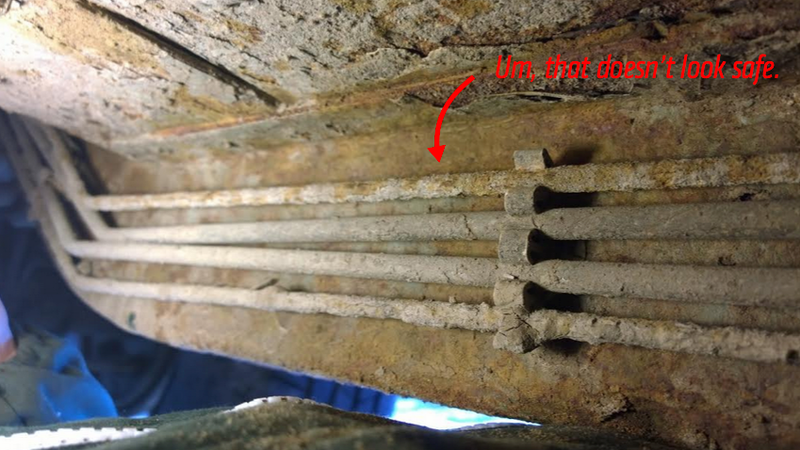
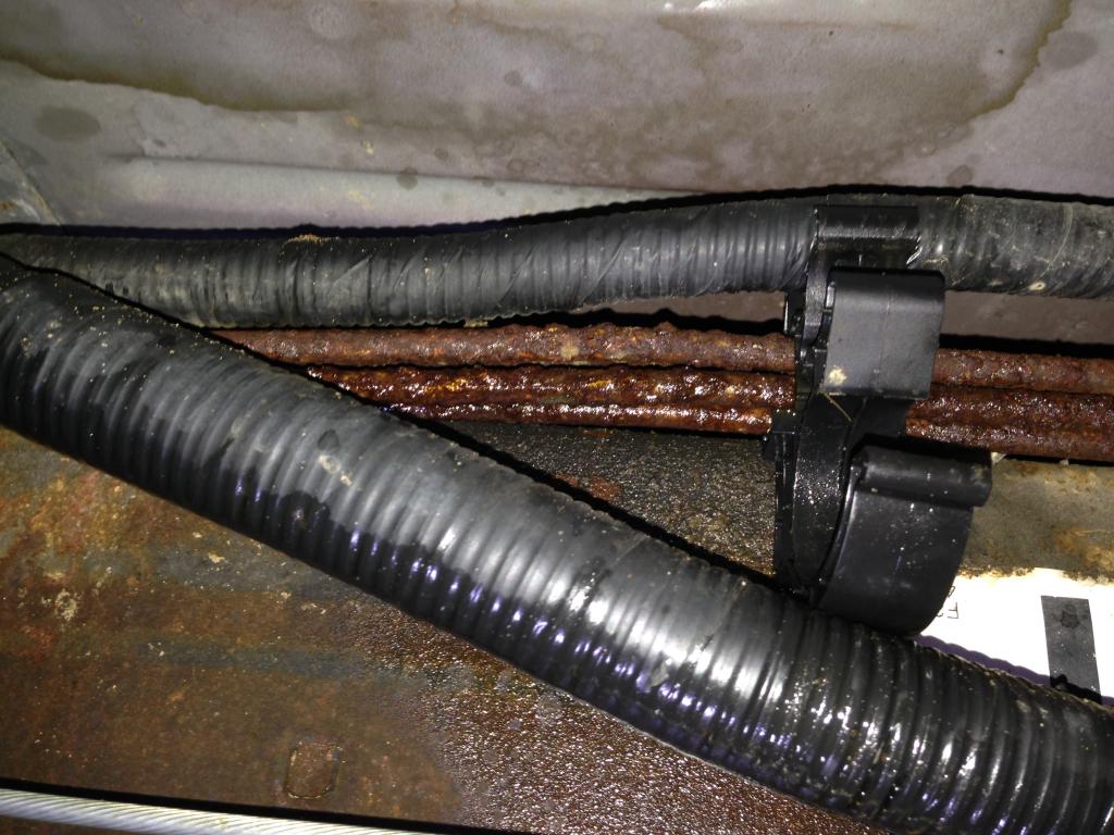
The brake lines run from the master cylinder(where you fill it with fluid on the drivers side firewall) down to the frame, and then follow the frame both directions; both to the front end and the rear end, along the drivers side frame rail, just on the inside of it. The fuel line runs along the same path to the rear. Posted on Oct 03, 2009. The power steering lines are very short hoses approximately 8 inches long that go from the power steering pump down to the steering box, which is located on the frame, just below the pump. The brake lines run from the master cylinder(where you fill it with fluid on the drivers side firewall) down to the frame, and then follow the frame both directions; both to the front end and the rear end, along the drivers side frame rail, just on the inside of it. The fuel line runs along the same path to the rear.
2002 Silverado Brake Line Routing
Mar 03, 2009.